MicroScribe G2 with RhinoCAM
a spatial measuring tool
- MicroScribe G2 is a three-dimensional measuring and digitizing tool. It is a precision mechanical arm based on optical encoders at each of five joints and connects to the USB or serial port of a computer. A software application interface monitors encoder position information and knowing the physical dimensions of the arm calculates the location of the hand-held probe tip.
MicroScribe G2 is a digitizer. It measures the location of user selected points in three-dimensions on the surface of an object. The XYZ coordinates are directly, automatically inserted into the active Windows application. 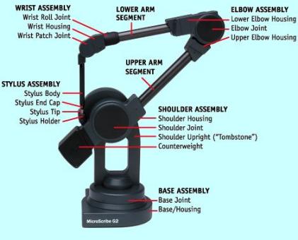 A sketch mode allows tracing a curve directly into Rhino.
Rhino or Rhinoceros is a three dimensional NURBS modeling program for Windows computers. NURBS, non-uniform rational B-splines, are precise, well known mathematical representations defining smooth curves, free-form curves, surfaces, shapes and solids. Rhino NURBS models may be exchanged among many software applications used for many processes - analysis, simulation, engineering, design, control, CNC machining, manufacturing, illustration, animation.
RhinoCAM is a machining plug-in for Rhino providing toolpath generation, cutting simulation and verification. RhinoCAM accepts Rhino modeling data and other file formats supported by Rhino. RhinoCAM supports a large selection of tools and toolpath strategies to create machining operations and associated toolpaths. Toolpaths are simulated, verified, and post-processed for the controller of your choice.
Rhino, includes support for the MicroScribe G2 digitizer. Digitized points are inserted directly into Rhino as absolute XYZ three-dimensional points with snap to grid off. A 3D digitizing toolbar includes several functions - connect, pause, disconnect, enter or pick a point,
sketch a curve, and create cross-sections.
MicroScribe G2 users indicate it would be difficult, impractical, or impossible to measure the location of points on the surface of an object in three-dimensions without a digitizer. They estimate digitizing is done in less than 5% of the time to do it, when possible, manually. A one week effort to determine spatial location of points would be completed in less than two hours. Rhino models may be exported to ProEngineer, SolidWorks,
SolidEdge, AutoCAD, CADKEY, Mastercam, 3D Studio, and similar applications.
setup
- at back of MicroScribe G2 base
connect USB (or serial) cable from host
power is provided by USB - red light (or power supply to +5V DC)
connect dual pedal foot switch to accessory
place probe tip in home position (in holder)
push home button to test and calibrate digitizer - green light (normal)
- open Rhino (or download Rhino for evaluation, install, open)
confirm 3-D digitizing toolbar is displayed
(or tools button, toolbar layout, check 3-D digitizing)
connect digitizer, mouse left click connect/disconnect button
select digitizer=MicroScribe digitizer, prompt (upper left Rhino windows)
(or left click digitizer indicated, highlight, select MicroScribe digitizer)
as prompted, digitize origin on desktop with probe tip & right foot switch pedal
digitize a point on x axis
digitize a +y point on the XY, Z=0 plane
enter on keyboard to select world origin
introduction to Rhino
- remember, the MicroScribe G2 is a spatial measuring tool inserting XYZ coordinates directly into Rhino
you design the model in Rhino
digitized points are absolute 3D, XYZ points
absolute XYZ points are not snapped to a grid or an object
as a guideline, digitize as few points as possible to define a curve
but as many as needed to capture the detail desired
digitize points defining curves - one curve at a time
- select perspective view
select circle, 3 points command button (vertical toolbar), notice prompt
digitize (right pedal) 3 points on desktop, circle is displayed
repeat last command (left foot pedal or enter)
digitize a few more circles at different 3D orientations
right mouse click zoom extents button (horizontal toolbar at top)
when done, clear screen - select all button and delete on keyboard
- enable Osnap (object snap), points to select digitized points with mouse to form curve or other object
use a set of curves to form a surface panel
join, merge, blend surfaces to form a model
shade, rotate model for visualization
render model for presentation
save model in format to be transported for CNC machining or analysis
- select point command (vertical toolbar), right mouse button for multiple points
notice location of probe tip is displayed as it is moved
XYZ coordinates displayed at lower left
enter a few points to define a curve in 3D space
enter ESC to end multiple point command
right mouse click zoom extents button
disable Snap (to grid)
enable Osnap, points to snap to digitized points selected with mouse
select curve, interpolate points function (from vertical toolbar button under points)
select points (Osnap) with mouse to form interpolated curve
left foot pedal or enter to end command
left foot pedal or enter again repeat last commend
when done, clear screen - select all button and delete on keyboard
- select sketch a curve with digitizer button in 3D digitizing toolbar
review, select options in prompt, key in spacing
move probe tip to start of curve
hold down right foot pedal
sketch curve
let up pedal at end
a set of digitized curves may be used to develop a surface
when done, clear screen - select all button and delete on keyboard
- open Rhino file surface on glass to see digitized points, edge curves and surface
rotate and pan perspective view
review shading options
- open Rhino help - review digitizing and the many functions for points, curves, surfaces, solids
REMTEK sells, markets and supports the MicroScribe G2 with Rhino and RhinoCAM - more information at our BEAT, a REMTEK newsletter
Let me know how can I help you?

ed@remtek.com or e-mail Ed
telephone 505-603-4073
* additional information
MicroScribe G2 User's Guide
REMTEK
RR 4 Box 30B - Hernandez, NM 87537
505-603-4073 - ed@remtek.com
©2007 REMTEK
2/28/07