MicroScribe G2 with Mastercam
a spatial measuring tool
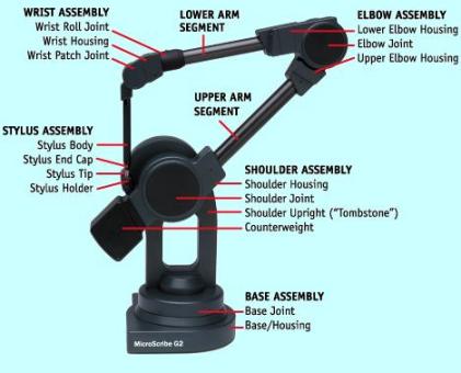
- MicroScribe G2 is a computer tool for a designer or engineer to measure the location of points in three-dimensional space or on the surface of an object. It is a precision mechanical arm based on optical encoders at each of five joints, embedded processor, foot switch, USB (or serial) connection to the users computer and a software application interface - MicroScribe Utility Software (MUS) . Using the hand-held probe and foot switch the user selects a point or sketches a curve (a set of points). Calculated digitized XYZ coordinates are directly inserted into a selected function in the users active Windows software design, analysis or control application.
- MicroScribe G2 is compatible with
... Rhino
... AutoCAD
... DesignCAD
... BobCAD-CAM
... CADKEY
... ProEngineer
... SolidWorks
... Mastercam
... Excel
... Notepad
all software application functions accepting keyboard entry.
setup
- at rear of base
connect USB (or serial) cable from host
power is provided by USB - red light (or power supply to +5V DC)
connect dual pedal foot switch to accessory
place probe tip in home position (in holder)
push home button to calibrate, test and connect digitizer - green light (normal)
- open MicroScribe Utility Software (MUS) (or download, install and open)
review welcome window or click OK to display digitizing window
move probe tip around, notice display of XYZ coordinates
- select format strings button
select Mastercam %.4f,%.4f,%.4f\n
- select configuration button
select standard (inches)
use comma as decimal (un-checked)
beep on plot (checked)
use scaling factor (un-checked)
use custom tip delta (un-checked)
- select reference frame button
select custom to define a user coordinate system
mark origin, X-axis, Y-axis on desktop (a drafting square is helpful)
digitize origin (right foot pedal switch)
digitize point on X-axis
digitize point on Y-axis
Z-axis is calculated at origin perpendicular to XY plane
OK
- open Mastercam
set Cplane 3D (main menu, click Cplane and 3D at top of menu)
set Gview Isometric (button at top or left)
select Create from Main Menu
select Line, Endpoints
notice Sketch highlighted and prompt at lower left
digitize origin and point on X-axis to construct line
digitize origin and point on Y-axis to construct line
digitize origin and point on Z-axis to construct line
click Fit button to fit axes lines to screen
from main menu select Analyze, Point & select orign to confirm ~ 0,0,0
repeat for points on the X, Y, & Z axis
- assure Cplane 3D & Gview Isometric
select create from main menu
select arc, circle 3 points (sketch)
digitize 3 points to form a circle
digitize a few more circles at different orientations in space
select fit to display circle
select
select Main Menu, Delete, All, Lines, Arcs to clear screen
- from main menu - create, point, position (sketch)
digitize 3 points to define a circle
esc to end command
from main menu - create, arc, circle 3 points (sketch)
select points using mouse
esc to end command
using a similar procedure create points for a set of splines
create spline, manual and using mouse to connect points
loft a surface defined by splines
....create, surface, loft - define contour 1, 2, 3, etc., done, do it ...
... Screen-Surface Disp-Shading
... Gview (Dynamic) to rotate view to examine the surface
- summary - points may be digitized directly into Mastercam functions supporting keyboard entry (sketch)
REMTEK
RR 4 Box 30B - Hernandez, TX 87537
505-603-4073 - ed@remtek.com
©2008 REMTEK
3/10/07