MicroScribe G2 with Pilot3D
a spatial measuring tool
- MicroScribe G2 is a three-dimensional measuring and digitizing tool. It is a precision mechanical arm based on optical encoders at each of five joints and connects to the USB or serial port of a computer. A software application interface monitors encoder position information and knowing the physical dimensions of the arm calculates the location of the hand-held probe tip.
MicroScribe G2 is a digitizer. It measures the location of user selected points in three-dimensions on the surface of an object. The XYZ coordinates are directly, automatically inserted into the active Windows application. 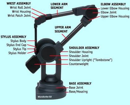
- MicroScribe G2 is compatible with
... Rhino
... AutoCAD
... DesignCAD
... BobCAD-CAM
... CADKEY
... ProEngineer
... SolidWorks
... Mastercam
... Excel
... Notepad
all software application functions accepting keyboard entry.
- Pilot3D is a relational trimmed NURBS curve and surface 3D modeling program. It includes processes to unwrap or flatten a 3D compound surface to allow it to be cut from flat material to be formed to the 3D compound surface. Review summary of capabilities at Pilot3D
setup
- make connections at rear of base
serial cable from host computer to serial
power supply to +5V DC in
dual pedal foot switch to accessory
place probe tip in home position (in holder) for calibration
turn power on
- open MicroScribe Utility Software (MUS) (or download download, install and open)
review welcome window or click OK to display digitizing window
move probe tip around, notice display of XYZ coordinates
- select format strings button
select (or create using Pilot3D as the window name) Pilot3D %.2f,%.2f,%.2f\n
- select configuration button
select standard (inches)
use comma as decimal (un-checked)
beep on plot (checked)
use scaling factor (un-checked)
use custom tip delta (un-checked)
- select reference frame button
select custom to define a user coordinate system
digitize origin on desktop using right foot pedal switch
digitize point on X-axis
digitize point on Y-axis
Z-axis is calculated at origin perpendicular to XY plane
OK
- open Pilot3D
- select options, snap options, check snap to points, 3D snap and OK
select options and snap ON
select top, front or right view (not 3D view) as active window
select point, add point, 'pick the location for the point', 'add point' display bottom display
digitize a few points in 3D space (XYZ coordinates briefly displayed at the bottom, just right of center)
select view, resize to fit to display entered points
using mouse place cursor on a point - notice XYZ coordinates at lower right
select curve, add curve - 'add curve' displayed bottom right
using mouse select (snap) cursor to point for start and successive points for curve
after last point is selected right click or 'enter' from keyboard
select 3D view, rotate view to see it is a 3D curve
to delete curve go to curve, delete curve and select curve with mouse
- summary
points entered with the mouse are 2D points
points digitized into top, front, right views are 3D points
with snap enabled, use mouse to snap to 3D points in top, front, right views to draw curves interporated through the points
commands are active (lower right) until another command is selected
(to snap to point in 3D view - options, toggle to un-check snap on (snap off), place cursor on point with mouse, enter 'p' from keyboard
review Geometric Entities for Pilot3D
REMTEK
RR 4 Box 30B - Hernandez, NM 87537
505-603-4073 - ed@remtek.com
©2007 REMTEK
2/28/07